 |
| November 12, 2013 | Volume 09 Issue 42 |
Designfax weekly eMagazine

Archives
Partners
Manufacturing Center
Product Spotlight
Modern Applications News
Metalworking Ideas For
Today's Job Shops
Tooling and Production
Strategies for large
metalworking plants
Simulating the rocket science of spacecraft liftoff
ATA Engineering uses Abaqus FEA software to reveal the multiphysics behind engine nozzle performance
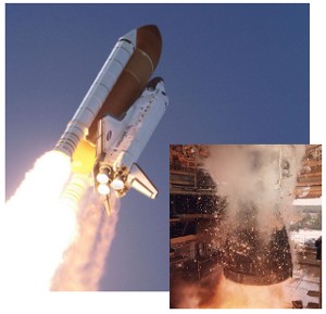
Every Space Shuttle launch gave the world iconic images of huge rockets powering the white spacecraft into Earth orbit atop billowing clouds of exhaust. The countdown before each liftoff was tense as millions watched the clock tick toward zero. At T minus 6 seconds, the three main engines would throttle up, their bell-shaped nozzles bursting into life and visibly shifting side to side as they channeled flames and supersonic exhaust to create an immense force that slowly lifted the shuttle into the air. Aided by twin solid rocket boosters on either side of the central fuel tank, the main engines burned at an average 6,000 deg F (3,315 deg C) with a continuous combustion of oxygen and hydrogen fuel that lasted a full 8 1/2 minutes during launch.
Throughout the 30 years of Space Shuttle flight, no mission ever failed because of the Space Shuttle Main Engines (known as the SSMEs). In the words of one NASA engineer quoted on the space agency's website, "If you don't build the engine right, you're not getting into space." After years of doing it right, NASA retired the Space Shuttle program in 2011 with the final flight of Atlantis. But the SSMEs, designed from the start to be reusable, now have a new life as part of NASA's ongoing Space Launch System (SLS) program to develop the heavy lifter rocket.
Taking weight out of a proven design, safely and cost effectively
The watchword of current Agency development projects is "budget." Flat funding means that every aspect of the program is geared toward keeping costs down while maintaining the highest levels of safety and performance. Rocket engines are not immune from such pressures. Reusing the SSME design was a logical step, given the engines' track record for reliability. But could their weight and performance be fine-tuned even further for the new rocket?
"Anything you can do early on in the engine design process to avoid surprises later on is going to help," says Eric Blades, director of Southeastern Regional Operations for San Diego-based ATA Engineering, Inc. His company has decades of experience designing, analyzing, and testing complex, highly engineered mechanical and electro-mechanical structures subject to severe dynamic loads in aerospace, defense, biomedical, automotive, and other products. ATA has been working on launch-vehicle and rocket-engine simulation and test for over 30 years.
"Conservative rocket design usually means making structures heavier," says Blades. "Heavier components create greater loads that require [the] supporting structure to be heavier. Every pound you can save with a more robust design -- a lighter design -- is more payload you can put into space. The better your prediction tools are for estimating the dynamic loads, the lower the safety factor and the lighter the weight you can achieve."
For a rocket engine, the nozzle can represent a large percentage of the overall weight. "Accurate prediction of nozzle loads during the immense stresses of liftoff can help identify opportunities to optimize the structure of the nozzle, providing reliable performance with less weight," says Blades.
And what a performance those nozzles have to give. Two seconds after ignition, they start to move and change shape. The fluid flowing through them separates from the interior walls and shifts to other locations within each nozzle in patterns that vary around the circumference of the nozzle.
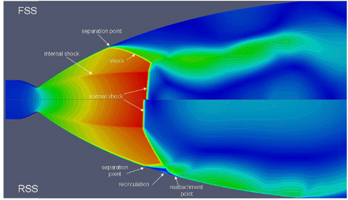
This results in an imbalance of forces, called side loads, which further deform the nozzles from round to oval, with a maximum deflection of several inches. These changes may appear minor, but at liftoff the results of these interacting multiphysics can greatly affect the integrity and output of the entire engine package.
Video: During engine startup, a shockwave forms at the nozzle throttle. As thrust increases, flow separates from the interior nozzle wall and continues as a free stream, sometimes deflecting back to reattach to the nozzle wall.
Simulation helps minimize the extremes of field-testing rockets
Rocket designers have been aware for quite a while that these types of fluid-structure interaction (FSI) events exist in nozzles, and over time their designs have attempted to mediate the consequences, with varying degrees of success. In the past, nozzle design assessments were primarily based on visual observation and ground tests. Results were not always ideal: In one non-NASA test, severe side loads in an overseas-designed engine caused the actuator to fail and break its regenerative cooling tubes. In another, the gimbal block retaining bolts for a similar engine failed because of high side loads.
Iterations of such real-world tests are time-consuming and expensive. What's more, says Blades, particularly with nozzles, certain properties "cannot be measured because the measurement devices themselves can't withstand the extreme test environment. Some of what we're interested in can only be determined through simulation."
An ongoing tool for simulation at ATA has been Abaqus finite element analysis (FEA) software from SIMULIA, the Dassault Systemes' 3DEXPERIENCE application. "As a methods development company in aerospace, we've had a long-term collaboration with Abaqus," Blades says. "We work with SIMULIA because they're interested in continuing to advance the methodology for simulating realistic physics. We see simulation as highly effective for driving and optimizing design."
Advancing fluid-structure interaction R&D with coupled analyses
A recent area of focus for ATA has been developing fluid-structure interaction simulation methods to evaluate engine nozzle behavior. Because of the wealth of knowledge and data available, the SSME was used as an example to validate these. Previous research at NASA's Marshall Space Flight Center had never been able to accurately simulate the effect of side loads on the nozzle's shape. The analysis always "uncoupled" the fluid dynamics from the structural dynamics because computational fluid dynamics (CFD) took so much more computing power. To work around that, analysts would make certain assumptions, such as the nozzle being completely rigid and perfectly round. These assumptions did not predict the shape of the nozzle during engine firing and did not lead to an accurate prediction of the total structural response of the nozzle.
ATA decided to test a comprehensive methodology that would couple structural and fluid dynamics into a full FSI analysis to arrive at a more realistic picture of rocket nozzle dynamics. The engineers employed the SIMULIA Co-Simulation Engine (CSE) capability to link their Abaqus FEA solvers with a flow solver -- in this case, the Loci/CHEM CFD developed by Mississippi State University (MSU), a code already used by NASA. Starting from a geometric description of the nozzle and a finite element model provided by Rocketdyne, ATA could call upon the wealth of shuttle rocket nozzle data already available from NASA to fine-tune their structural and fluid models.
The CSE was the software "glue" that tightly integrated the two solvers with mechanisms that provide data synchronization and transfer information for several solvers running concurrently. It has a mapper to transfer information where the surface- and volume-based data overlap, and it has an application programming interface (API) for client simulation programs. (For example, the CSE API is available out of the box to connect the Abaqus structural solver to CDadapco STARCCM+ CFD; no additional code is necessary.)
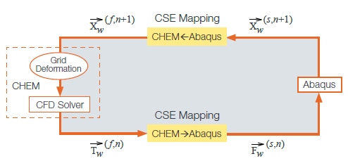
ATA's FSI simulation methodology employed Abaqus FEA, CHEM CFD, and the SIMULIA CSE to couple FEA and CFD simulations together. Mesh displacement calculations are repeatedly exchanged between the two solvers at each time step.
The FEA structural model included the rocket engine gimbals, the gimbal actuators, the stiffener bands around the nozzle, the main combustion chamber, and the nozzle itself. The fluid model was based on values for a "single-species gas," which represented the combined characteristics of the hydrogen and oxygen in rocket fuel. The mesh for the fluid domain was created with a mesh generator developed at MSU.
During an FSI simulation, the CHEM CFD solver analyzes its fluid mesh, computes the forces of rocket propulsion on the mesh, and transfers the results of those computations through the SIMULIA CSE to the Abaqus structural solver. Abaqus analyzes the engine structural mesh and generates the structural displacements due to the loads from CHEM. These displacements are transferred back through the CSE to the CFD model in CHEM, which updates the fluid mesh to reflect the new deformed shape of the nozzle and reanalyzes the fluid mesh accordingly. This back-and-forth cycle repeats for every time-step in the simulation.
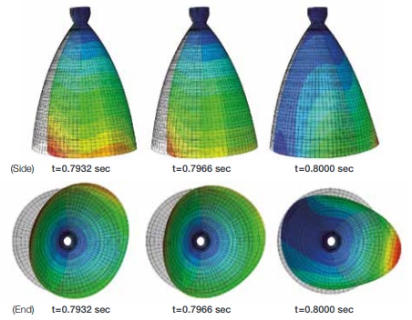
A side and end view of the nozzle deformed shape and deformation contours during unsteady FSI simulation. The maximum total displacement over the time interval shown occurs at the trailing edge of the nozzle.
ATA ran two FSI simulations in sequence to gain a complete look at nozzle dynamics. The first run determined the shape of the nozzle moments after SSME ignition. "We didn't have the computational resources to simulate those initial seconds when not much was going on, but we needed to get the shape of the engine when things started to get interesting," says Blades.
The result from the first simulation determined the initial shape of the nozzle for the second simulation, which gave NASA an idea of how the nozzle deforms, the amount of deformation, and the side loads involved. The simulations of the low-frequency structural response of the nozzle were consistent with earlier physical observations of the SSME during test and operation. "All of our predictions were in line with what NASA was expecting," says Blades.
A first in rocket nozzle simulation
"These simulations using Abaqus and CHEM CFD early in the engine-startup sequence represent the first-ever fully coupled, time-accurate, 3D FSI simulation of a rocket engine nozzle," says Blades. "And while the coupled simulations were more expensive than the CFD-alone simulations NASA currently performs, they weren't prohibitively so. The CPU requirements are within reason."
ATA's next step is to fully validate their FSI simulations to demonstrate the accuracy of the co-simulation methodology. "NASA and others in the rocket-engine community may want to use this technology to better represent the physical phenomena in aerospace applications," says Blades.
The chances of that happening are good: ATA was recently selected to continue their work within NASA's SLS program. "Next-generation launch systems will require propulsion systems that deliver high thrust-to-weight ratios, increased trajectory-averaged specific impulse, reliable overall vehicle systems performance, low recurring costs, and other innovations to achieve cost and crew-safety goals," says Blades. "The existing SSME, on which we based our recent work, will be used for the main stage of this rocket, and NASA is also looking to use our FSI simulation methodology to design the upper-stage engines."
Source: Dassault Systemes - SIMULIA
Published November 2013
Rate this article
View our terms of use and privacy policy